Computer Organization and Design, 5th ed.,
by David A. Patterson and John L. Hennessy
Morgan Kaufmann Publishers, 2013
The
simulator is written in Java 8 (javafx) as a stand-alone application and delivered
as an executable jar file (PathSim.jar).
Dr. Dalton R. Hunkins
hunkins@sbu.edu
Computer Science Department
St. Bonaventure University
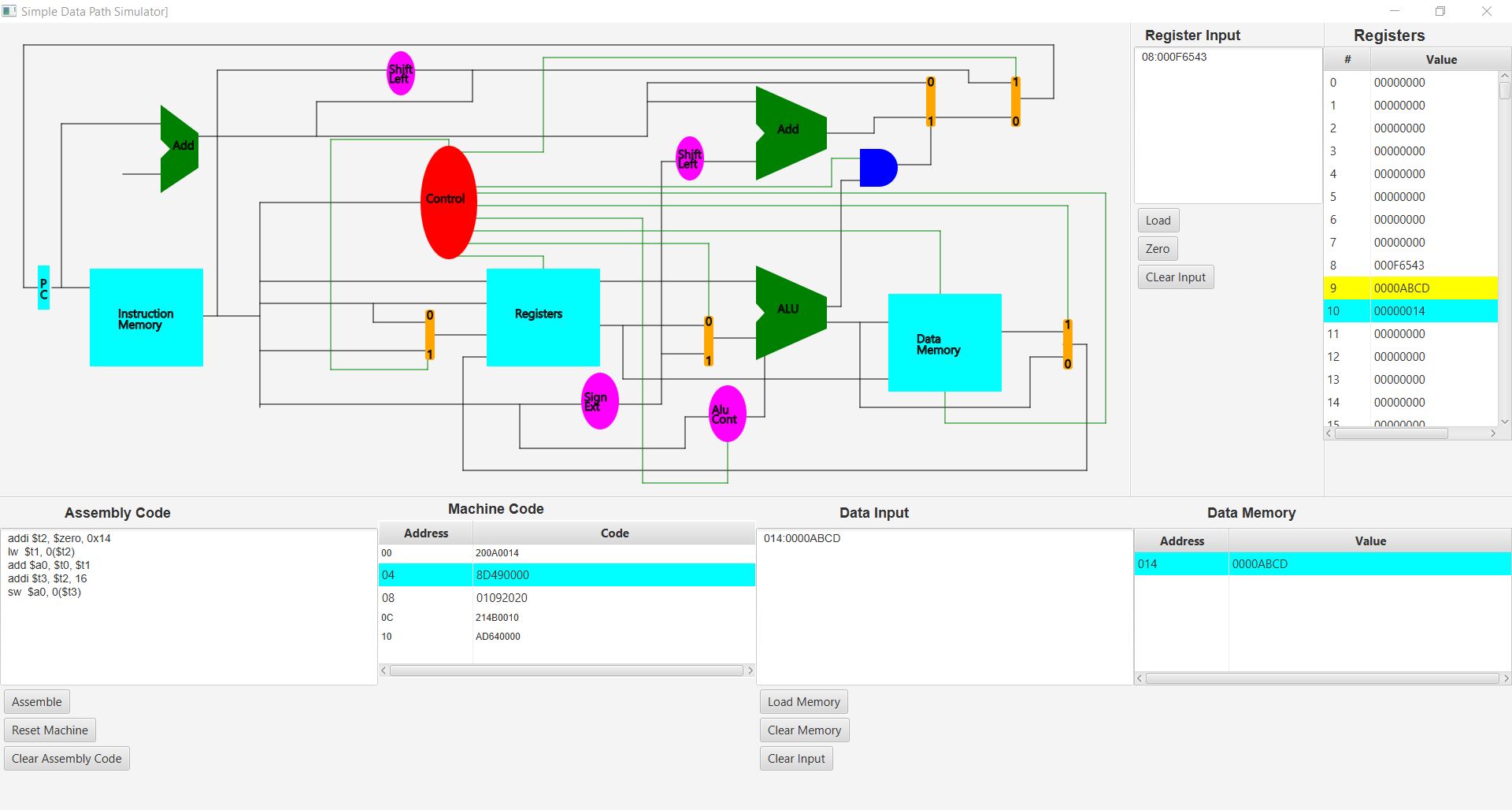
As seen in the above image, PathSim
is composed basically of four areas: the architecture schematic shown in the
upper-lefthand panel, Assembly Code and its Machine Instructions, Data Input and Memory, and
Register Input and the Registers. Each of these is discussed in the following
sections.
The diagram of the architecture is
basically that shown in Computer Organization and Design, 5th ed., chapter 4.
The diagram given here is interactive. You can single-step through
execution of mips instructions by left-clicking on the cyan rectangle labeled
PC -- one instruction per click. The machine instructions being executed are those
assembled from those given in its textarea (input box). Also, the
assembled instruction appearing in Machine Code area that was just
executed is highlighted in cyan. You can see the effect of an instruction on the
data path by placing the mouse over a data line and left-clicking. In doing so,
a white box pops up displaying the current value on that data line.
Assembly Code and
its Machine Code
The assembly code you plan to
execute is written into the textarea labeled as such. Text-editing can be done
within this textarea but you might find it more convenient to create your code
in a plain-text editing tool apart from the simulator and copy-paste the code
into the textarea. In this way, you can save your code to a file (the
Assembly Code textarea does not provide for opening nor saving a file). There
are three buttons appearing in the panel, namely, "Assemble" ,
"Reset Machine." and "Clear Assembly Code."
Pressing the Assemble button invokes the PathSim assembler, which, in turn,
assembles the code written in its textarea. If the assembler should find an
error according to its syntax, an alert box appears showing the
"offending" line of code and the error. The PathSim assembler is a
"first-error-and-out" assembler. This means you must fix an error and
assemble the edited code before proceeding to the next error, if any. You will
see the assembled code in the Machine Code table when your assembly code is error free.
Pressing the Reset Machine button resets the program counter (PC) to 0 and
resets the particular data addresses and registers to what was last loaded; all
others are reset to zero. This means that it is not necessary to re-load these
using their respective load buttons. If no values were previously loaded, then
all data addresses are reset to empty and the registers are reset to 0.
Pressing the Clear Assembly Code button simply clears the input textarea so as to start
fresh in entering assembly code.
Assembly code for PathSim does not
contain any labels for branch points (e.g. loop:) or jump addresses. Instead of labels, we use
signed integers representing the number of Words as the offset in a branch instruction. The format of
such a branch can be given as an decimal signed number or as a hexadecimal number
with the standard 0x prefix. The absolute address of a jump instruction must be
given in the hexadecimal format.
Also, we do not use directives such as .text, .data, etc. In turn, storing values
in data memory is done through Data Input.
Except for these differences, the rest of the syntax for the PathSim assembler
is the same as for a mips assembler (e.g. QtSpim). Last, each line of code must
be terminated with an end-of-line marker.
The five Rtype instructions add, subtract (sub), and, or, and set on less than (slt) along with the data transfer instructions load word (lw) and store word (sw) and the instruction branch on equal (beq) are discussed in chapter four in the simple data path context. Additional instructions are implemented in PathSim. The additional instructions are the Rtype instructions xor, nor, sllv, srlv, and srav and the Itype instructions addi, andi, ori, and xori. The two instructions j and bne are also implemented in PathSim.
The Data Input box is also a Javafx textarea and,
in turn, you can type your data values here. But you may also want to consider using a separate plain-text
editing tool and copy-paste into the text-area.
The format for a line that is entered into the textarea is
memoryAddress:value. Both the memoryAddress and the value are strings of
hexadecimal digits. The string for the value must contain exactly 8 hex digits and
that for the address must contain exactly 3 hex digits. The 0x prefix is not
given with either of these. Also, there cannot be any spaces surrounding the colon (:)
nor any other place in the line and there cannot be any empty lines (i.e., null
strings terminated by an end-of-line marker). Last, each data input line must be
terminated with an end-of-line marker.
The Data Memory area is for displaying your data values that are loaded into
data memory when you press the "Load" button. You can clear the memory by
pressing the "Clear Memory" button and clear the input
textarea by pressing the "Clear Input" button.
When you step through the execution of your instructions, whenever a reference
is made to a word in data memory, the word is highlighted within the display
area. If the reference is for reading, the highlight is cyan; if it is a
write-reference, then the highlight is yellow.
As with the other input textareas, the
Register Input area is a Javafx textarea. Therefore, you can type your register
values here. Of course, we only need to do this when we want to initialize a
register with a value other than zero (0 is the default initial value).
The format for a line that is entered into the input box is
registerNumber:value. Similar to data values, a register value is a string of
exactly 8 hexadecimal digits. On the other hand, the registerNumber must be
written as an unsigned decimal (base 10) number, 0 through 31. Also, there cannot be any
spaces surrounding the colon (:) nor any other place in the line. Last, each
input line must be terminated with an end-of-line marker and there cannot be
any empty lines.
The Register listing shows the register values either as initialized with zero or
as loaded from Register Input when you press the "Load"
button. The "Zero" button sets all registers to 0 and the "Clear Input"
button clears the input textarea.
When you step through the execution of your instructions, whenever a reference
is made to a register, the register-value is highlighted within the display
area. If the reference is for reading, the highlight is cyan; if it is a
write-reference, then the highlight is yellow.